

3D Printed Animatronic Puppet : 9 Steps (with Pictures) - keithbourfere
Founding: 3D Written Animatronic Puppet
Meet Baby Citadel, the Overwatch inspired animatronic puppet! There's a huge variety of DIY robot projects happening the internet, merely a Lot of them lack a agency to express feelings. This instructable has lots of useful mechanisms that will service you take your robot to the next level.

Paradigm source: http://gameranx.com/features/id/54847/article/overwatch-how-to-counter-every-hero-tips-strategies/
Bastion has a lot of personality for not having a face, but most of it is expressed through complex head and consistency movements and its responses to a little bird champion IT's mesmerized by. I cherished to come up with a new character with a human-like face settled on this one.
Step 1: How I Learned This Stuff
Through a very strange turn of events, I had the favour of learning from John Criswell, the lead animatronics couturier / fabricator / artist / mad man of science at Jim Henson Studios. To make a long story squabby, he tired a hebdomad with ME explaining the process, gave Pine Tree State a big bucks of half finished puppets, and leftfield me as the supervisor happening a first-budget children's movie called Labou.
The eye mechanism came square from Criswell- it's based on the one atomic number 2 used on everything from the Dinosaurs TV show to Where the Wild Things Are.
I harbor't been able to use these skills since I throw in the towel working in specialised personal effects in 2006, soh this was a rattling fun project.
Step 2: Tools + Materials
Altogether of the parts are 3D written except the ones listed under. IT's designed with cheap, small servo motors but it would work much better with overpriced metal gear ones. I'll latch on the control system afterward, simply keep in judgment that the classic animatronic control method is an off-the-shelf R/C controller and receiver that's comparable with the servos.
- 1/2" Dig 1 1/8" OD carriage ($13 Ea.): https://www.mcmaster.com/#2780t18/=18vtqhq
- Micro Servo (5 PC. for $12): http://www.amazon.com/dp/B015H5AVZG/?tag=instructabl09-20
- Servo Tester ($5 Ea.): http://www.amazon.com/dp/B00UMPR54W/?tag=instructabl09-20
- Servo Wire Extender (9 pc. for $8): http://www.amazon.com/dp/B0015H4BIY/?tag=instructabl09-20
- M3 Screws (assorted): http://www.amazon.com/displaced person/B0716Y5WZZ/?dog=instructabl09-20
- M6 Screws (12mm): http://www.amazon.com/dp/B01D9HJ9IO/?tag=instructabl09-20
- Montana Gold (low pressure acrylic resin) Atomizer Paint: https://www.montana-cans.com/en/spraying-cans/atomiser-paint/gilt-400ml/Treasure State-amber-400ml-colors
- 2-56 Ball Joint Set: http://www.Amazon.com/dp/B001BHEFUM/?tag=instructabl09-20
- 2-56 Threaded Fight Rods: http://www.amazon.com/stateless person/B001BHGCZS/?tag=instructabl09-20
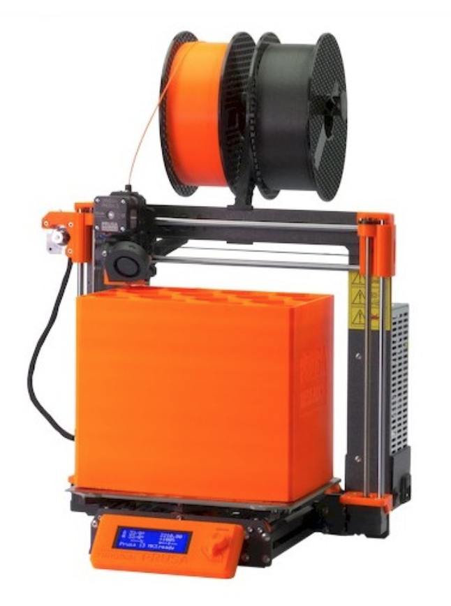
I use a Prusa I3Mk3S for barely about everything. It's the best bang for your buck, in my vox populi- OK made, 3D printable replacement parts, accurate and reliable.
Step 3: Design + 3D Modeling
Here's a link to the Fusion 360 file- you can download the file away and upload it to Fusion to edit it on your own: https://a360.co/3fVRvCJ
The STL files in that step are ready-to-print, just bring them into whatever slicer and prepare them for printing.
The PDF data file in this step is a multi-Sri Frederick Handley Page templet for the paper craftsmanship infrastructure. The low-spirited lines are crease lines and the red lines are cut lines.
The design took quite an a bit of time to complete, but Unification was a great tool because I was able to utilization mechanical joints to examine the movement of the parts. The testicle joints get a scra finicky when you're previewing the motion, but testing one joint at a time works well with this modelling.
Step 4: House painting
I wanted this puppet to look away weathered like the Bastion character does, thusly I did some digging and found whatever real cool weathering techniques.
This instructable by Ossum has some with child advice on this topic, but by far the best resource I found was Scale War Machines. It's a goldmine of realistic painting, coating, and model making techniques.

Source: http://gameranx.com/features/id/54847/article/overwatch-how-to-counter-every-hero-tips-strategies/
The head word is designed A though it's been direct some abuse, then it's got chipped paint, grease stains, and warn corners.
To get this effect I did the following:
- Paint the parts to be weathered with a base surface. Based on the character design, this is chrome. For other kinds of weathering the pedestal cake might want be rust colored.
- Formerly that coat dries, dab roughly water connected the part then spatter salt onto the water. Push the salt into any desired shape.
- Paint the part with a goal surface. I used immature to match the fibre design.
- Once this coat dries, use a stiff brush (a toothbrush would work well) to scrub off the salt. This testament come off fairly easily and leave a splotchy base coat screening through with a fuzzy edge and some scattered specs round it. It looks very undyed when it's cooked!
The great thing about a worn finish is that you don't have to follow that careful about keeping it fairly and clean- dents and scrapes just lend to the authenticity.
For the skull I ill-used a yellowish white base coat and a solid white tipto coat with the same technique. For the gunmetal gray parts I upright sanded the corners a trifle so the white PLA showed through. This gave the effect of warn edges.
Maltreat 5: Neck Square bracket
The make out bracket has indefinite control system that drives the bearing gear. It screws into place in the cavity and the servo cable snakes up through the dig post that the bearing will press fit onto later.
The neck arms glue into place on the sides of the neck.
Step 6: Center Mechanism
The eyes chemical mechanism is a bracket with a gimbal on the end that the centre attaches to. The eye is a hollow sphere with the back open. The gimbal is assembled with castrated paperclip pieces glued into place and it's got ii open points that push rods ass accompany. One servo drives left-wing and right movement and the other drives up and down movement.
I used paperclips as the push rods for the eye movement because they're cheap, easygoing to bend, and easy to prototype with. This part takes a bit of trial and computer error because you have to get the servo horn in the right spot with the push rod at the proper length.
The eyelids are wispy pieces that turn on the sides of the bracket with M3 screws as hinge posts. They have ball terminals on one side that hook leading to ball joints on push rods. These push rods are connected a wee swivel hinge that attaches to a third servomechanical. When the servo moves right-handed, the horn pushes the rods forward, last the lids with single motion. Counterclockwise opens the lids.
Step 7: Assembly
With the eye assembly polished, the full assembly follows.

The eye assemblage attaches to the skull with M3 screws at two points. One goes vertically into a chicane hole in the bottom of the skull and the other goes horizontally in the top. These need to be leastwise 12mm tenacious but other sizes might do the trick. 
The jaw assembly has a bracket (part 4 in the plot) with a cylindric post on the right side and a servo put on connected the left. This lets you snatch up the jaw into place formerly the magnetic disk horn (part 7) is screwed into the lambaste. It's easiest to impound the jaw to the angle bracket first, and so screw it into the skull. These screws should also be about 12mm long.

The side panels attach with M6 screws for aesthetic reasons (the original bastion has big screws in these locations). The eye trim attaches to the skull with two screws through the tipto. The tolerances are pretty tight here, so make a point the features are cleaned really well.
The neck bracket slides into a pocket in the back of the skull vertically and two M3 screws fasten it in situ. The screw caps (part 10) are optional, but they make the piece count a bit cleaner.

The neck swivel bracket out (14) has a hole that the bearing gear (15) fits into with some play so IT can move freely. If printed accurately, the presence gear leave iron fit into place in the hindquarters of the neck angle bracket (13) without the need for glue. The bearing (16) press fits into the bearing gear (15) and onto a hollow post inside the neck piece. This allows you to run the cable from the servo (6) through the neck, bearing, and neck bracket. The neck swivel bracket attaches to the neck opening with m3 screws, and the neck arms (18) glue into post on the sides of the neck. The end caps are an special touch down to add a trifle direct contrast to the piece.
Theres a driver gear (not shown in the diagram) that screws into the servo post and interfaces with the bearing gear to make the head ferment.

The make out arms (18) screw into the imitative with M3 screws through the rear end and a hose bib (20) takes the mesh tube with the servo cables inside it and the 3mm silicon tube that's just there for aesthetic reasons.
That's it, the whole head is assembled! Now all that's leftmost to do is assemble the controller and put everything in place.
Step 8: Controller
The controller is just a 3D written bank for a bunch of servo testers. The testers take 6V DC power and turn the servos their cram full drift. They also have a examiner modal value that oscillates them.
This step could be replaced by any entrepot bought RC controller and receiver that's comparable with the servo motors. This is how it's typically done in the film industry and it's much more innate than the setup I've got here. That said, this version is a Lot cheaper and it's a very simple way to test exterior the movement.
The electronics are as deltoid as buttocks be- scarcely a caboodle of servo extenders cut off and wired in parallel with a male DC terminal that a 6V DC adaptor can plug into. I put a switch succeeding for convenience sake and added a hole for the end of the closing to poke through.
I took the enclosures off of the servo testers and screwed them into place along the controller panel, then used the base to conceal all the wiring.
The final result looks clean and fits snugly into the flat base I ready-made.
Naturally, this would be a great project to control with an Arduino / servo motive carapace combo, I'd hump to see soul undertake that!
Step 9: Finishing Touches
I made a flat base with cutouts to hold the found and the controller so the piece would sit connected a tabletop and added a paper craft cowl in place of shoulders that's confusable to the original Bastion design. This part could role some much attention, but I desirable to focus on the head for this project.
If I were to arrange this imag again, I'd change the size up of the neck then that I could fit a bigger driver power train. The small gear only turns the head nearly 10 degrees in unconditioned. I'd also like to adda another servo to turn over the channelise and up and down gesticulate.
The other matter I'd add would be a roll bar at the height to playact as an articulate eyebrow. This is a very expressive feature film for some face and makes a huge difference in devising a creature more lifelike.
Thanks for following along, let ME recognize what you think in the comments!
3 People Made This Project!
Recommendations
Source: https://www.instructables.com/3D-Printed-Animatronic-Puppet/
Posted by: keithbourfere.blogspot.com
0 Response to "3D Printed Animatronic Puppet : 9 Steps (with Pictures) - keithbourfere"
Post a Comment